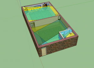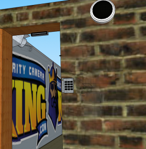
After you have decided that you have a need for a surveillance system and you’ve worked through what kind of system you want to use, you are going to run into the question of how many cameras you need and where are you going to place those cameras. One tool for determining this is to create a model or floor plan of your facility or home. There are more than a few advantages to doing this: The first is being able to get a rough overview of the coverage you are going to have and an approximate view of what the cameras will be able to see without actually installing them. The second way floor plans and modeling can be used to assist you in placement is allowing you the ability to see where your cable runs may need to go, and also allow you to get an estimate on the measurements of cable length you may need. Finally, if you are an installer, floor plans and models allow you to create accurate examples for co-workers, employees, and clients about what to expect in installing in a building and viewing their surveillance system. This article will explain the advantages of modeling your surveillance camera positions.
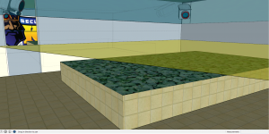
Once you have a rough idea of what areas of your residence or business you want to have camera coverage, you can start conservatively estimating where on your floor plan you would want to place the cameras and what their approximate coverage would be. A physical walk-through of the residence or facility is always advised prior to plotting cameras on your layout as there are fixtures and features that may not be visible on your floor plan or take up too much time to place on a model. With the locations mapped, as we discussed in the first paragraph, you can begin plotting out the viewing angles and coverage. In the examples I’ve created for this article you can see I’ve marked the cameras with yellow blue and green viewing angles. This allows us to observe just which cameras are covering what areas and how we can attain 100% coverage of this greenhouse. Doing this will take some adjustment and some research into which cameras provide what kind of viewing angles and exactly where placing these cameras will give you optimal coverage. A rough guideline for 1/3 inch chip set can be found here.
It is important to note that this is a rough estimate and camera optics can vary depending on a variety of construction, placement and installation considerations. As such, there is a limit to estimating modeling and floor plans and conservative calculations should be made when creating your model or layout. When we at SecurityCameraKing.com (TechPro Security Products) prepare digital models or floor-plans/layouts, we often include these margins of error in order to provide a better estimate with more satisfying results. But again this is still just an estimate and exact measurements are best reserved for installers with direct perspective when and while installing the equipment to acquire the best results. In fact it is best to always remain flexible and prepared as measurements can differ from modeling by a significant margin.
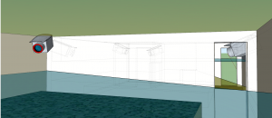
Next we can use our floor plan and models to assist us in placement by allowing us the ability to see where cable and power may, or should need to be, run for optimal results all the while minimizing costs by plotting out the shortest runs possible. Plotting these distances will give us rough estimates of how many feet of cable will be needed from the Digital Video Recorder (DVR) to camera, and from camera to power supply. Since most runs are installed through the attic it is recommended that you include ceiling measurement and estimate extra cable for avoiding obstacles in the ceiling, such as air conditioning conduit etc. Even with these advanced estimates it is always possible to experience the unexpected, so try not to undercut cable lengths too exacts as it is always possible to encounter a hindrance that could not be expected by modeling, and one that may change the route of cabling entirely.
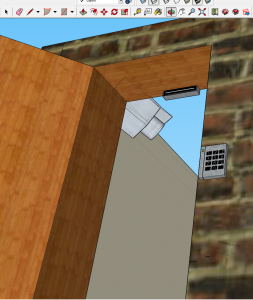
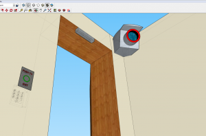
This can also be exceptionally valuable with access control as power supplies and battery backups increase the amount of equipment being physically installed. With the increase in equipment as expected there is an increase in wiring which also can help to plan out by modeling. The level of detail to be included in a model is limitless, however it is recommended not to go too in depth because as with close caption television surveillance systems, access control system installation can differ from the model when it comes to the physical installation. For example an expected convenient place to put a push to exit button or reader, may actually have significant conduit containing wiring behind the drywall that did not leave you enough space. So try not to be overly detailed in your placement and expect to be flexible in your instillation. Despite the potential for differentials between model and physical install, modeling will give you a significant advantage in what to expect. It is also convenient to show customers how access control systems may work and this can give you a significant edge over a competitors quote.
Finally, if you are an installer, models and floor plan / layouts will allow you to create accurate examples for co-workers, employees, and customers to be able to see what your goals and expectations are for their surveillance install. The advantage of modeling in the competitive industry of installation and monitoring cannot be over emphasized. The ability to not only explain the coverage and services provided, but visually exemplify it are unparalleled. We here at SecurityCameraKing.com regularly construct and design surveillance floor plans for our customers. This allows us to give our customers and installers an accurate idea of what kind of placement to look for and an edge when building virtually any size systems. Again this is not for exact detail but is an excellent way of gaining a better understanding of where and how your cameras should be placed.
