As you may all know SecurityCameraKing.com serves The Surveillance Industry as well as the Access Control Industry. These two industries are different from one another and it can be overwhelming when installing or troubleshooting your system, mainly because transitioning from surveillance equipment to access control is not the same. Access control requires some knowledge of how circuits work. In this article, I will go over some basic circuit knowledge that will allow you to install or know what to do in a case where you will need to troubleshoot your system. This knowledge can come in handy especially in an emergency situation.
Lets start by going over open and closed circuits.
When a device has a label that reads “Normally Open” this means that in a normal state there is no electric current flowing through the circuit. Think of it as a momentary switch (ex. door bell) when the button is depressed it completes the circuit this allows the flow of electricity and the device will turn on a chime in the case of a door bell.
Lets see how a door bell circuit works.
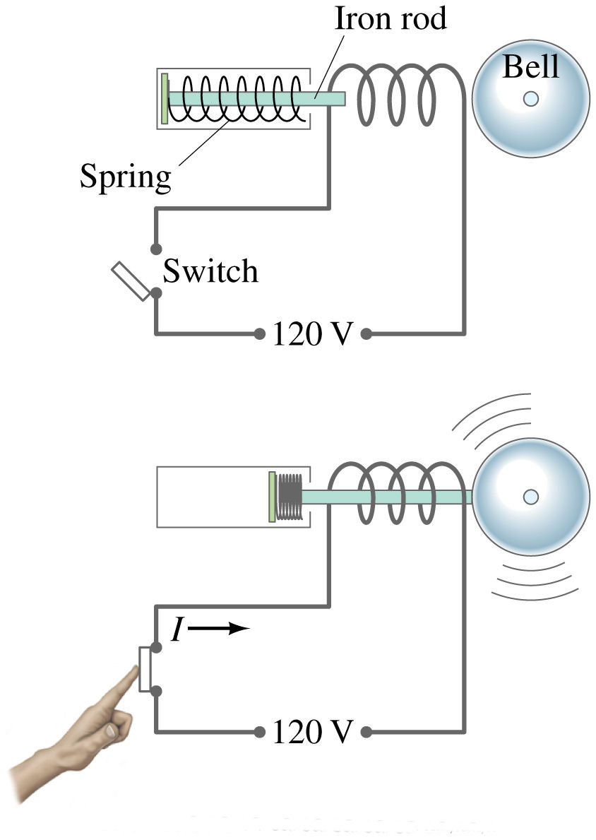
The image on the top illustrates the circuit in an open state where there is no flow of electricity, the image on the bottom shows the circuit in a closed state where electricity will flow, allowing the coil on the electromagnet to become energized and with the assistance of a spring giving you the ringing sound.
Now that we know the differences between open and closed circuits I will go over how an access control panel functions and then we can move on to see how they should be connected and why it is very important to know these two basic circuit functions (Normally Open and Normally Closed).
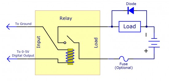
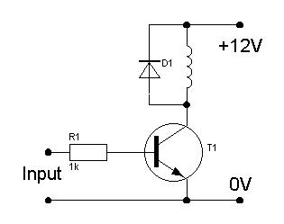
An access control system is simply a controller that triggers ON or OFF circuits by means of relays. This means that any output from the relays can turn ON or OFF [Open or Close Circuits] devices such as a Mag Lock, which is a high powered Magnet that is normally rated in pounds. Closing the circuit in a MagLock will create an Electromagnetic bond that keeps the door closed until there is an input from a reader to the control panel. The control panel opens or closes the circuit using its relays. The diagram shown below illustrates how a Mag Lock functions in the “Control Panel”. In this case it is the “Switch” part.

Lets see how a “Strike” circuit works. As you can see it works similar to the Mag Lock where the circuits closes and a coil will retract a rod that will allow the person to gain entry. This is called a solenoid.
Here is a Video on how this is accomplished.
Now that we have covered the basics, let’s move to some other details such as Fail Safe devices. These are devices that even when there is no power the device will continue to be in a locked position, keeping the door secure. Fail Safe devices are typically door strikes.
Electromagnetic Lock Types.
With Door Status Switch: This device will show an open or closed door status to the system, allowing you to know if there is a door that is malfunctioning or someone has propped the door with an object.
With Delay: This will give you a few seconds before the mag lock will release the door. This is most common in a high security area.
The use of Mag Locks or Door Strikes are the most popular ways to control the entry or exit of a building.
Lets see how a one door system with a stand alone controller looks like.
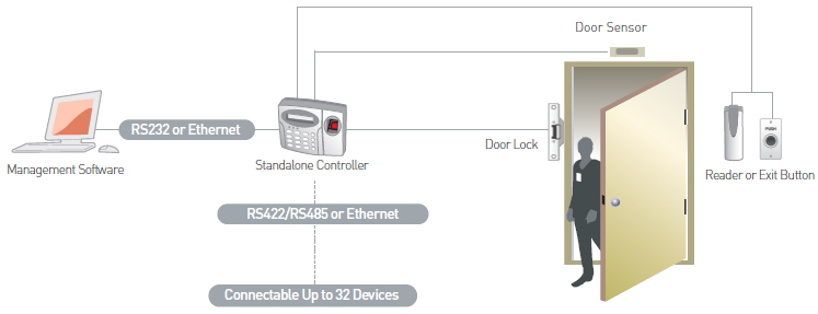
This is the easiest way to get a small business with only one door up and running with their access control. In the picture above, we see a Door Lock [Door Strike] connected to the Stand-alone controller with door sensors, as well as an exit and Reader. The user identifies himself with the use of a Card or Keyfob at the reader which sends a signal to the controller. The controller goes in its database and sees that this user has access and then completes the circuit to the Door Strike allowing the person entry.
Seems simple?
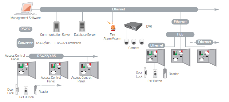
Lets try it with a control board instead of a standalone. This is good for a medium size business. In this illustration you will see integration with other devices such as a surveillance system by using its alarm outputs. We can now use the cameras as another form of a motion sensor. We can also integrate the system with a fire alarm panel. There is a lot of possibilities, and it is all about knowing the limitations of each board and system.
Lets move on to battery back up and the use of fuses and Diodes.
When it comes to any security system, one will have the needs to keep these systems running even when there is not power present in the building, either by a malfunction of the Electrical System or by tampering.
There are different capacities of inverters such as 200VA, 250VA, 350VA, 400VA, 450VA, 500VA, 625VA, 1200VA, etc. The capacity of the inverter should be chosen based on how much watt of appliances you power at a time.
For a UPS with 875Va we can use a maximum load of 640 watts. For a UPS with 677Va we can us a maximum load of 540 watts
The main thing we have to understand is that whatever may be the UPS wattage, the battery backup will not vary. The battery backup will only vary depending on the battery Ah and the Usage Load.
To calculate UPS backup, We have a simple formula.
UPS Backup = Battery Ah * (Volts/Load) * (1/Powerfactor)
For Example:
Lets calculate the back up for a system UPS
Load is the usage power. Suppose we are running a PC then the load is around 300 watts.
Power Factor varies for device to device, the average power factor is 1.4
Voltage is the voltage of the battery.
For a single battery the voltage is 12v.
If the batteries are connected in a series Voltage = 12 * no. of batteries.
Battery Ah is the battery ampere used for the ups,
System UPS battery AH is 7
Then Battery Backup
= 7 * (12/300) * (1/1.4)
= 7 * (0.04) * (0.7)
= 0.19 hours
= 19 Minutes
Note: You can use the same formula for calculating the battery backup for UPS or an INVERTER.
Battery back up systems can become complex if you are looking to power the devices for more than 30 minutes. Knowing how to calculate what you need is crucial when purchasing the correct back up system or building your own.
This also functions for a Solar Power system. In the case of a Solar Powered System you will have to take into account the Solar Cells as well as the location and knowing peak Sun hours. Here is an article that goes into detail in regards to solar power.
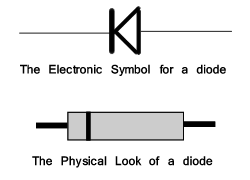
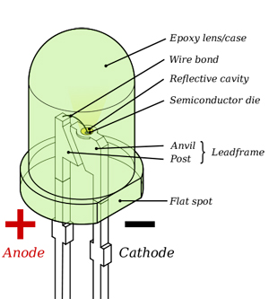
Lets move on to the Function a Diode can have on an access control System. For this we need to know what a Diode’s function is. A diode is a small device with two terminals [+ side is called the Anode and the – side is called the cathode]. This device allows the flow of current only in one direction. This means that in a case where there is malfunction and there is a device with a short, it will protect the device by not allowing current to flow back into the circuit.
Fun Fact: ;P
A Diode can be found on Light Emitting Diodes also known as LED’s. They work by electroluminescence. Try saying that 3 times, lol. They work in the same principal where the + side [Anode] and the – side [cathode] and a Semiconductor crystal is in between these two. Depending on the semiconductor is the color that it will emit.
Lets move on to Fuses.
Fuses are devices that have have a small strip of metal, usually encased inside a cylindrical glass with two ends that connect to a terminal. They are widely used in the electrical industry as well as the electronic industry. These devices will allow current to flow, but when the amperage is high above its rating the small strip inside will melt, cutting electrical flow while preventing damage to the circuit.
The Fuse is represented by these symbols.

Now that you know about how the circuits work when it comes to Access control, you can safely install your equipment as well as make a wise decision as to what you need. Keep in mind that the conductors carrying the signals from one device to another is also important, as well as grounding properly each control board if utilizing more than one. Consult our Sales team for any questions that you may have and we can also assist you with Designing the perfect system for your needs.


