Many of our customers call us to ask why they cannot change the camera’s position when using a built-in POE NVR. The short answer to that is that it is not possible after the cameras are connected for the first time on the NVR. See, the NVR’s POE built-in switch is a separate entity. The idea behind this technology is to offer security, avoid broadcast storm, and in theory separate the traffic from the IP cameras and NVR completely. Also, the most obvious reason to use a built-in POE on these NVRs is to power the cameras from one unit, without using an external POE switch. This will reduce the cost of equipment in theory.
So, why can I not move the cameras to a different position after I plug them in the NVR? Well, the reason is that the MAC Address of the cameras “Sticks” to the port the camera is connected to, and the NVR will not release that unless the NVR gets defaulted completely.
What can I do if I want to change the position of my cameras then?
Ahh, that’s why I’m writing this article, to show you an idea I have that I think could help many customers that are frustrated with this type of setup.
NOTE: Although this article is solely to show a temporary fix to the way the POE works, it is intended to be used ONLY on those NVRs with POE built in. In the near future, a firmware will “fix” or add a different way to accomplish the following task. Any camera added to the built-in POE switch will not be accessible over the LAN interface. Instead, if you would like to access the settings of the cameras, you will then use the NVR’s web interface (EL SERIES IPC ONLY). For ONVIF cameras, you will need to be connected with a computer to one of the ports of the built-in POE Switch and either assign a static IP on your PC Ethernet card or simply get an IP address from the POE switch IP pool. You will then be able to change any settings on the camera.
The Following list will show you the NVR models numbers with Built-in POE:
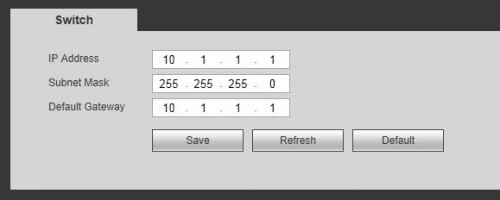
Lets begin by understand the settings on the NVR. The POE switch, like I said before, is a separate entity from the regular single LAN port. Normally the single Ethernet port of the DVR IP address is 192.168.1.108. The POE side is by default 10.1.1.1. You can change this by going to the network settings. For this article I will be using the web service interface of the NVR. Click on Setup, from the left options, click on Network then all the way to the bottom click on Switch.
Notice that the IP address and default gateway are in the same range, in fact they are the same number. If you planned to change this then you must have the same number on both the IP address and gateway. Also, the IP address here and for the NVR cannot be on the same range. An example is if the LAN port is configured 192.168.1.X where X is a random number from 1-255 then the IP address from the switch side cannot be on that range. You can leave the defaults as is and you will not have any conflict, or if you want to change it to something similar then you can use something like 192.168.x.x where the (x.x) can be any number different from your LAN IP Address.
The next step is to make sure you configure the essential settings for your NVR. Time, Date and DST are essential settings to keep your cameras in sync with the NVR time and to make sure the recordings have the accurate date and time in case an event happens.
Go to Setup>Setting>General and Date&Time. Adjust the date format and time format based on your liking.
Go ahead now and connect the cameras to the POE switch of the NVR. For this demonstration I have 2 cameras connected with a short CAT5e cable. Allow about a minute for the cameras to show up on the screen of the NVR. NOTE: If for some reason the cameras do not come up on the screen, there is a chance that the IP cameras’ IP addresses are set to static and the NVR does not know how to change it to dynamic. Simply disconnect the camera and put it on a external POE switch and change the address using the config tool. You can download the tool here: CONFIG TOOL 2.0.
Assuming that all the cameras are set to dynamic, you should start to see the video streaming in the NVR. Also notice that you can tell when a camera is added automatically to the NVR by checking the LAN Icon displayed in the top left corner. This indicates that the camera is detected for that channel.
I have a total of 4 cameras connected on this NVR. Two of these are connected directly to the unit and two are brought from the network. The next thing to do will be creating a tour that will basically rearrange the cameras the way you want it. Ideally it will be easy for you to make a note of the IP cameras’ channel and what channel you want them to appear. For example, if camera 1 and 3 are not on the channels you want, then all you need to do is create the tour and select the cameras in the order you want them in the tour screen. If you want camera 3 on channel 1 then click on channel 3 first, that indicates the tour that the fist camera in the group will be #3. For this example I will choose camera 3 to go on window 1, camera 4 on window 2, camera 1 on window 4, and lastly camera 2 on window 3.
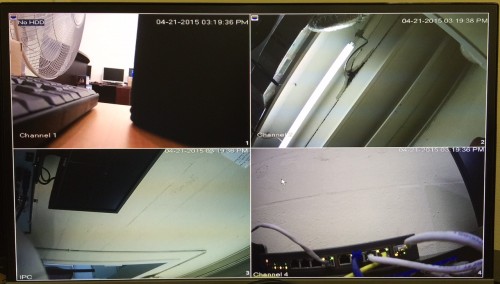
Below is a picture what it looks like before enabling the tour:
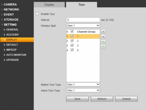
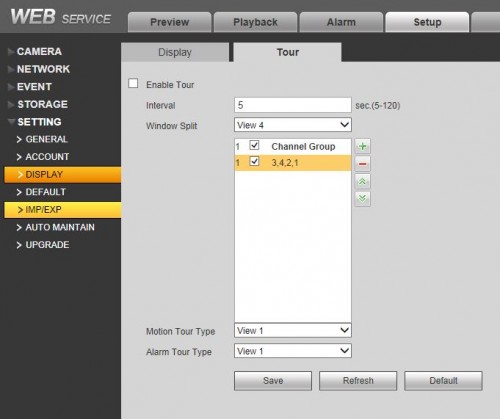
To configure the tour, login to the NVR and click on setup>settings>Display>Tour.
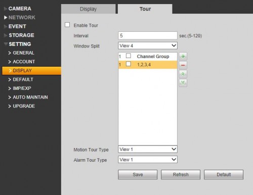
Notice that the NVR has different views (Window Split). On this NVR (4CH NVR ELT) I only have View 1 or View 4. For this trick to work, you will need to uncheck all of the channels on the View 1 channel group. This will ensure that the tour will only display a 4 View Split. From the window split drop down select View 4.
Now in this window, delete the current view of cameras then click on the Green + button to add your own. Like I said before I will click on cameras 3, 4, 2 and 1 to add the view on my screen.
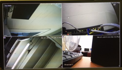
Click on Enable and click on Save. Now this is how my cameras are arranged at this point. NOTE: Due to the nature of the Tour, the screen will refresh every 5 seconds. You will see that the screen goes dark and comes back for a second. I will recommend you to set it to 120 sec so you don’t see the refresh of the screen often.
DISCLAIMER: The purpose of the tour is to arrange the cameras on the main screen. The arrangement of the cameras will not be displayed when viewing the cameras over the web service. Also, in the event of searching for footage, the camera arrangement will not be paired to the channel in the footage. An example of this is if camera #4 was showing originally on channel 1 prior to enabling the tour, then when searching footage for that camera you will need to select channel 1 since that is the original window of the camera in question.

