Since there are a lot of Pan Tilt Zoom (PTZ) Cameras available, I will explain in this article on how to best choose the correct PTZ for your Security Camera Installation.
I will start by showing the different parts of a PTZ camera.
1. Parts of a PTZ camera
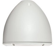
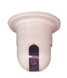
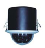
(a) Housing – Usually composed of an aluminum bell shaped cover (image 1) or some models have abs plastic housings (images 2,3)
|
Image 1 |
Image 2 |
Image 3 |
 |
 |
 |
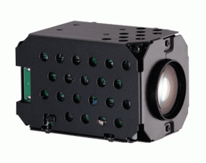
(b) Camera module
This is where the image CCD sensor, optical lens, and the motors that control Zoom and Focus are located.
(c) PTZ control board
The PTZ control board processes RS485 data that converts it into mechanical movements.
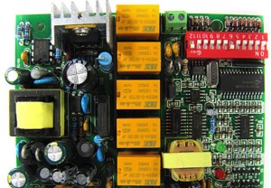
Note: On this particular PTZ control board it has dip switches (the red block with white switches). This allows you to change the protocol and ID of the camera. Some of our cameras are configured via the OSD (On Screen Display) menu.
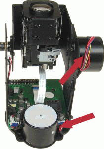
(d) PTZ motors – are the small motors that allow the camera to perform up, down, left and right functions. Marked by the arrows are two step motors; the one to the top controls up and down movements and the one at the bottom controls left and right movements (Image 1).
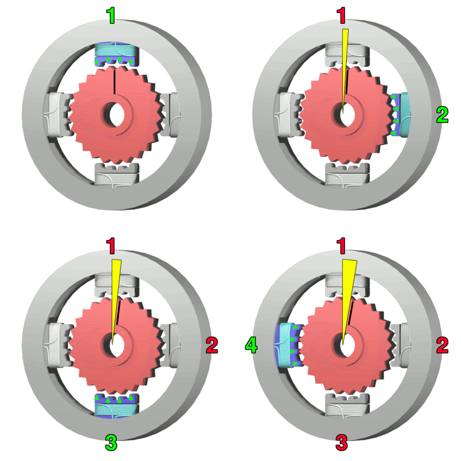
Note: The motors used on a PTZ camera are known as step motors which use steps (teeth) that allow a more precise movement vs. standard electromagnetic motors that require higher RPM’S and torque. Below are the two animated examples of an electromagnetic motor (image 2) and step motor (image 3).
|
Image 1 |
Image 2 |
Image 3 |
 |
 |
 |
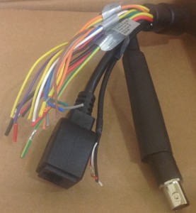
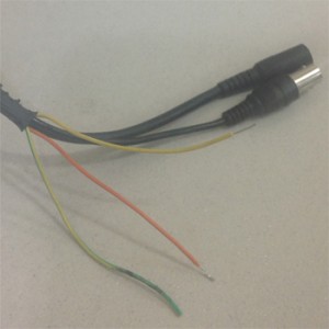
(e) PTZ Pigtail – is the cable that comes out of the camera which allows you to connect power, video, network, audio and alarms.
The Standard size IPPTZ cameras have alarm, audio, analog BNC out and an RJ45 jack (image 1). Mini-IPPTZ do not have an analog out option.
Our analog PTZ cameras have rs485, ground, BNC analog out and DC power plug (image 2)
|
Image 1 |
Image 2 |
 |
 |
Note: RS485 is a simple protocol used for communication between two or more devices. The nature of RS-485 allows transmission of PTZ data along side power or in electrically noisy environment without interference. It has been tested to work at 1600 ft. on CAT6e cable.
2. Technologies
Currently our PTZs come in three different technologies
1. Analog
2. IP
3. HD-CVI
(a) Camera cable run limitations and options to extend if necessary
Analog has a 1000 ft. Video and RS485 Range but can only be powered up to 150 ft. before voltage drop. Two ways you can counter the power limitation is by:
1. Having power at the camera
2. Using a power supply with a higher amperage rating. An example of that would be if your camera is rated at 500 ma and your run is over 150 ft – use a 2-5 amp power supply. Although theoretically it should work we do not recommend exceeding the 150 ft. limit
IP has a 300 ft. limit due to standard networking limitation. Since power, video and RS485 can be run on a single CAT6e cable there is no way to increase the range without additional equipment. In the event you have to exceed the 300 ft limit you can use a POE injector that allows you to extend an additional 300 ft.
HD-CVI has 1600 ft. video and RS485 limit. You can use CAT6e for both the RS485 and Video; for the video you will need video baluns to allow 1600 ft. range. The power has the same limitation as the analog cameras and will required local power or a higher rated 12v 2-5 amps depending on the camera requirements.
(b) Video quality and Resolutions
Analog – Our analog cameras come with 700 TVL
IP – Range from 1.3 Mega Pixel, 2 Mega Pixel, and 3 Mega Pixel
HD-CVI – Currently only supports 1 Mega Pixel (720P)
(c) What are differences between IP, analog + HD-CVI
1. An analog camera has to be physically connected into the DVR to record video and has a limitation of 1000ft.
An IP camera does not have to connect directly to an NVR. Simply by configuring some the network you can access your camera anywhere in the world. Let’s say your camera is in California and your NVR ( Network Video Recorder) is in New York. You can actually record the video from that camera at your New York location. This type of setup is used frequently by government and cities to monitor remote cameras.
2. Both the IP and HD-CVI support HD resolution, 720P and 1080P, whereas the analog only supports D1 resolution at 700 TVL
Note: The higher the resolution of a camera, the larger the images. It allows for wider coverage areas and more details vs the analog resolution. Because the images are larger on higher resolutions its better suited to use the digital zoom to get a closer look at an object.
3. Mini and Standard size cameras
Two of the major differences between our mini and standard sized PTZ cameras is the size of the housing and the optical lens capacities. The mini cameras are more aesthetically appealing in smaller homes and offices. The larger housings are better suited for larger homes and commercial applications.
|
Mini-PTZ |
Standard Size PTZ |
 |
 |
4. Camera modules
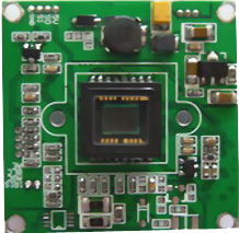
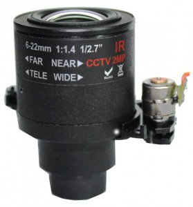
(a) The camera module houses what is called the CCD or CMOS board (image 1), lens and motors that allow fine adjustments of zoom + focus (image 2).
|
Image 1 – CCD OR CMOS board |
Image 2 – PTZ lens with control motors |
 |
 |
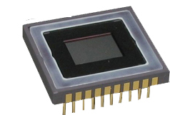
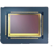
(b) Image Sensor – captures light and converts it into a digital image that can be stored onto the DVR/NVR. Currently there are two different types of sensors, CCD and CMOS. There isn’t much difference as far as image quality, but the CMOS sensors are known to handle brighter than normal scenarios extremely well. The CCD sensors were designed for IR applications where cut filters and automatic shutters are used. But in the past few years with advancement in technology, cameras now offer WDR (Wide Dynamic Range) and IR cut filters (Infrared Cut filters) which allows digital and mechanical adjustment for your specific setup. So it doesn’t matter if your using a CMOS or CCD as your end results are of high quality.
|
CCD Sensor |
CMOS Sensor |
 |
 |
(c) Optical lens – Allows for adjustment of zoom or focus. When you zoom in, the lens moves closer to the image senor so the image becomes larger. When you zoom out the lens moves away from the image sensor which make the image small and results in a wider view. When referring to 12x zoom on lets say our PTZ-LX700L12X mini it means it can zoom in 12 times the normal amount. Generally you can find out what the range on the lens is by multiplying the lens size by the times zoom. So in our PTZ-LX-700L12X you can multiply 5×12=60. Five being the lens size multiplied by zoom gives you maximum mm size of 60 mm. In this case this camera has a varifocal range of 5-60mm
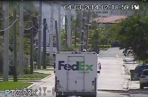
Here is an example of our 23x PTZ camera. The approximate distance from the camera to the truck is 380ft.
6. Mounting options
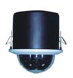
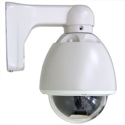
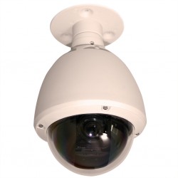
PTZ cameras are designed to rotate a full 360 degree there for an arm mount (image 2), pendulum mount (image 3) or ceiling mount bracket (image 1) is used for mounting the cameras.
Ceiling mounts- A ceiling mounting is great for any application that requires a PTZ camera but with a low profile. The better half of the camera goes into any surface and has a clip mechanism to secure it. Only the dome will be visible for a aesthetically appealing look.
Arm mount- Are designed to mount a vertical plane or post. Generally this camera serves as a deterrence as it protrudes from where its mounted
Pendant mount- are designed to hang from a horizontal surface such as ceiling, post.
| In ceiling mount | Arm mount | Pendant mount |
 |
 |
 |
7. Wiring PTZ cameras
(a) Wiring RS485 for Analog PTZ cameras
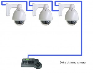
There are two ways you can successfully wire PTZ cameras 1. Daisy chain 2. Star or direct connection
|
Daisy Chain connection |
Star or Direct connection |
 |
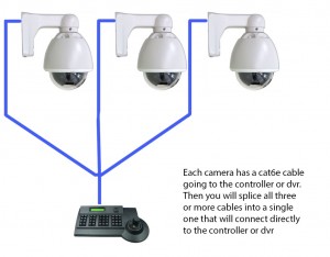 |
Note: Recommended cable CAT6e but CAT5e works fine as well. Use a single pair ex: solid blue and white/ blue, use the solid blue as the positive and the white/blue as the negative.
The main difference between daisy chaining or direct connection is on a daisy chain the cameras rely on each other. So if one fails the ones that follow the failed camera will not work. On a direct connection the cable is ran directly from each camera to the controller or DVR. I normally splice in a 2-3 ft. cable to make it easier to connect. If a camera fails none of the other cameras are affected and continue to operate as normal.

